Step 6 - Engine Sounds
When ClearView converted the aircraft it uses a default engine sound. For many aircraft with a glow engine this is probably satisfactory. If you have a model that uses a four-stroke, turbine or electric then you probably want to use a different sound.
The decathlon that we are currently converting is an electric powered model so the internal combustion engine sound is in-appropriate.
ClearView uses .wav format sound files. Luckily FMS also uses the same format. If you look in the directory where the original files were extracted you will see a w decathlon.wav file. If you play this file you will hear an electric motor sound.
To change the model sound in ClearView copy the w decathlon.wav file to the w decathlon/wavdata directory. Change its name to plane.wav replacing the file already there with that name. ClearView will play the correct engine sound when flying the model.
You may however notice that although ClearView plays the correct engine sounds it still displays exhaust smoke. Now since this is an electric model, smoke is not a good idea. This can be changed in the params.txt file.
ClearView understands if a model is electric or internal combustion (needing smoke) by examining the 'planeType' parameter. If the parameter is 0.0 this is an internal combustion model and smoke is displayed. If the parameter is 1.0 the model is electric and no smoke is displayed.
Sometimes the engine sound in the FMS files is not what you desire for your model. Any suitable .wav file can be used as an engine sound though it should be kept relatively short, two to three seconds is generally sufficient. ClearView will just keep repeating the clip indefinitely.
A good source of the correct sound is an actual recording of the engine. Generally a recording of an engine at around half to three-quarter throttle sounds best. If this is not possible then you can always use the sound from another model that has one that you like. Please remember though that you are copying someone else's work and should ask them if they mind and respect their wishes. Look in the model's readme file for the author's information.
Since we are discussing smoke, internal combustion engines (including turbines) generate smoke. ClearView is able to display smoke, the exit point and its direction is controlled by two entries in the params.txt file.
- smokeExostPoint - This is the point at which the smoke starts
- smokeExostVect - This is the direction the smoke initially travels in
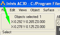
Both parameters use an x, y, z reference. Obtaining the setting for the exhaust point is done using AC3D. The easiest way to do this is to create a single vertex as you did for the control points in step 4. You can then easily move this around to get the best start location. The x, y, z position can then be read directly from AC3D. The picture shows the coordinates for a point just under the engine cowl. Once you have the coordinate the vertex can be deleted.
Setting the vector is a little harder. A vector determines an end point relative to the start point and is therefore not an absolute figure. There are various ways to determine the vector, with experience of vectors you can set this directly from within ClearView.
Perhaps the easiest way is to use AC3D. Draw a line from the exit point of the smoke in the direction you want it to initially travel. This is shown in the diagram.
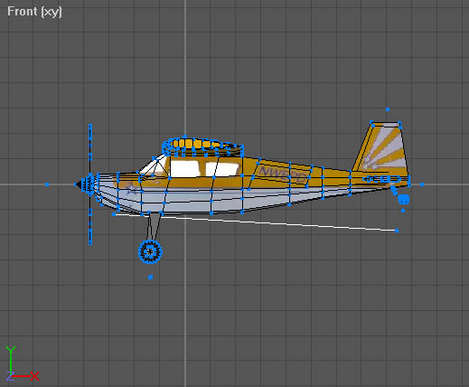
This temporary line gives you all the information you require to set both parameters. The coordinates of both ends of the line are:
| Ā | X | Y | Z |
|---|---|---|---|
| Initial point | -0.285 | -0.118 | 0.0 |
| Vector point | 0.836 | -0.182 | 0.0 |
To find these points switch to vertex mode and select each of the end points in turn, the coordinates are displayed as discussed earlier.
The vector is based upon a simple subtraction. Subtract the initial point from the vector point.
| Vector point | Initial point | Result | |||
|---|---|---|---|---|---|
| X | 0.836 | - | -0.285 | = | 1.121 |
| Y | -0.182 | - | -0.118 | = | -0.064 |
| Z | 0.0 | - | 0.0 | = | 0.0 |
This gives you a vector of 1.121, -0.064, 0.0 which then gives values for both parameters of:
- smokeExostPoint -0.285 -0.118 0.0
- smokeExostVect 1.121 -0.118 0.0
One other point to note is that ClearView will only generate a single smoke stream. If you have a model with two or more engine exhaust outlets then place the initial point at a position further back behind the exhausts. This will simulate where the streams would naturally join together.
Note: If you examine the parameters of the included models and some add-on models you will see that the smokeExostVect has been normalised to have the largest vector as 10. If you wish to do the same you can simply scale the individual values appropriately.